MCU는 ATSAMD21G18A을 사용하였고 관련 데이터 시트는 아래 첨부했습니다.
코드 분석
void Timer_Init() {
  /** Divide the 48MHz clock source by divisor 6: 48MHz/6=8MHz, Select Generic Clock (GCLK) 4 */
  GCLK->GENDIV.reg = GCLK_GENDIV_DIV(6) | GCLK_GENDIV_ID(4);
  while (GCLK->STATUS.bit.SYNCBUSY);

  /** Set the duty cycle to 50/50 HIGH/LOW, Enable GCLK4, Set the 48MHz clock source, Select GCLK4 */
  GCLK->GENCTRL.reg = GCLK_GENCTRL_IDC | GCLK_GENCTRL_GENEN | GCLK_GENCTRL_SRC_DFLL48M | GCLK_GENCTRL_ID(4);
  while (GCLK->STATUS.bit.SYNCBUSY);

  /** Enable GCLK4, Feed the GCLK4 to TC4 and TC5 */
  GCLK->CLKCTRL.reg = GCLK_CLKCTRL_CLKEN | GCLK_CLKCTRL_GEN_GCLK4 | GCLK_CLKCTRL_ID_TC4_TC5;
  while (GCLK->STATUS.bit.SYNCBUSY);

  //counter in 16-bit mode, waveform generation operation for match frequency, 256 prescaler
  TC4->COUNT16.CTRLA.reg |= TC_CTRLA_MODE_COUNT16 | TC_CTRLA_WAVEGEN_MFRQ | TC_CTRLA_PRESCALER_DIV256;
  while (TC4->COUNT16.STATUS.bit.SYNCBUSY);

  // Set the compare and capture value of channel 0 of TC4 to 62500
  TC4->COUNT16.CC[0].reg = 62500;
  while (TC4->COUNT16.STATUS.bit.SYNCBUSY);

  //Enables an interrupt for the Timer/Counter4 module when the timer value matches the value set in Compare Channel 0 (MC0).
  TC4->COUNT16.INTENSET.bit.MC0 = 1;

  //Connect TC4 to Nested Vector Interrupt Controller (NVIC)
  NVIC_EnableIRQ(TC4_IRQn);
}
GCLK(Generic Clock Controller)
광범위한 클럭 주파수를 제공할 수 있는 9개의 일반 클럭 생성기를 제공합니다.
1) GCLK->GENDIV.reg = GCLK_GENDIV_DIV(6) | GCLK_GENDIV_ID(4);
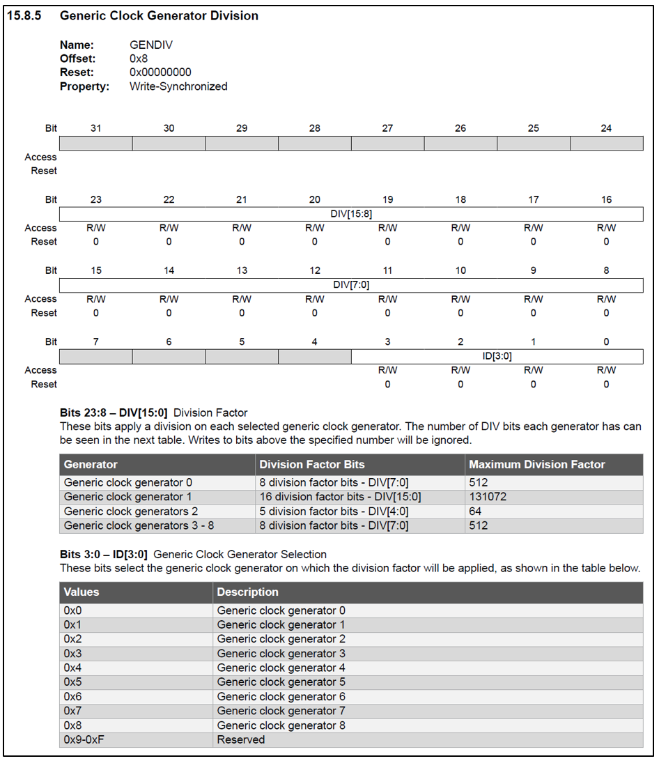
48MHz 클록 소스를 6으로 나눕니다.(48MHz / 6 = 8MHz)
Generic clock generator 4를 선택합니다.(GCLK 4)
2) GCLK->GENCTRL.reg = GCLK_GENCTRL_IDC | GCLK_GENCTRL_GENEN | GCLK_GENCTRL_SRC_DFLL48M | GCLK_GENCTRL_ID(4);
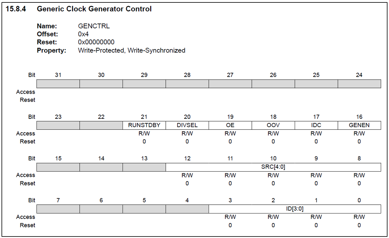
① GCLK_GENCTRL_IDC

듀티 사이클을 50/50 HIGH/LOW로 설정합니다.
② GCLK_GENCTRL_GENEN

GCLK4를 활성화합니다.
③ GCLK_GENCTRL_SRC_DFLL48M
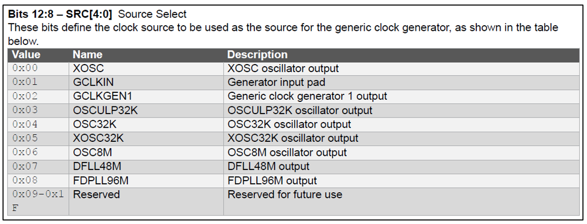
DFLL48M(48MHz) clock source를 설정합니다.
④ GCLK_GENCTRL_ID(4)
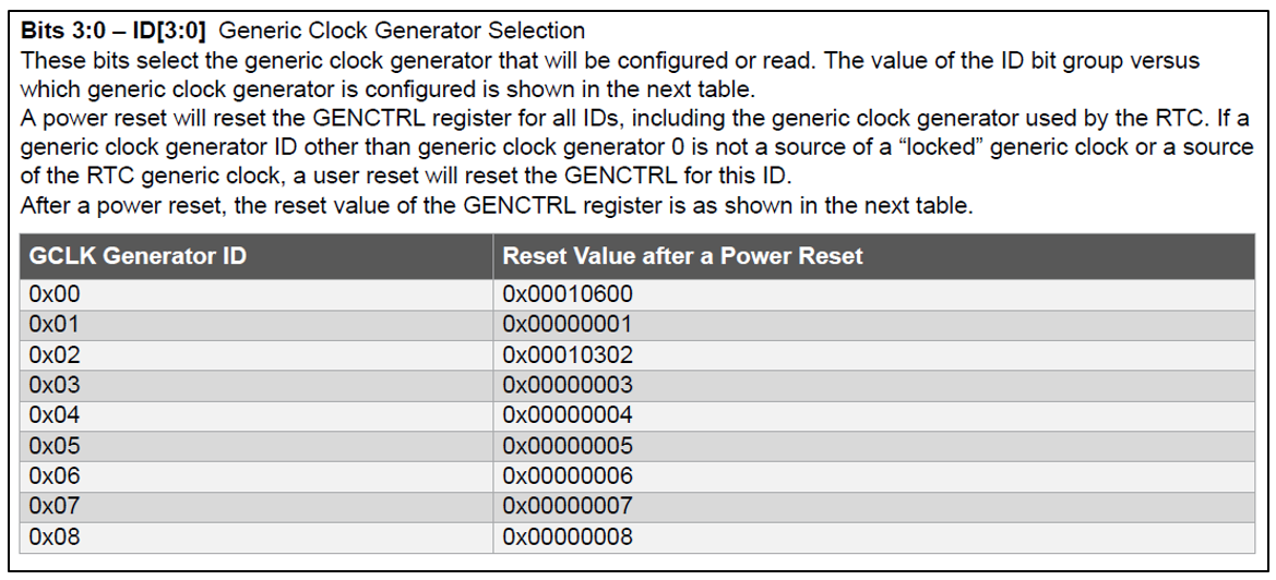
Generic clock generator 4를 선택합니다(GCLK 4).
3) GCLK->CLKCTRL.reg = GCLK_CLKCTRL_CLKEN | GCLK_CLKCTRL_GEN_GCLK4 | GCLK_CLKCTRL_ID_TC4_TC5;
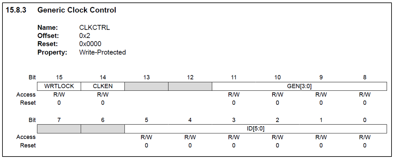
① GCLK_CLKCTRL_CLKEN

Generic clock을 활성화합니다.
② GCLK_CLKCTRL_GEN_GCLK4
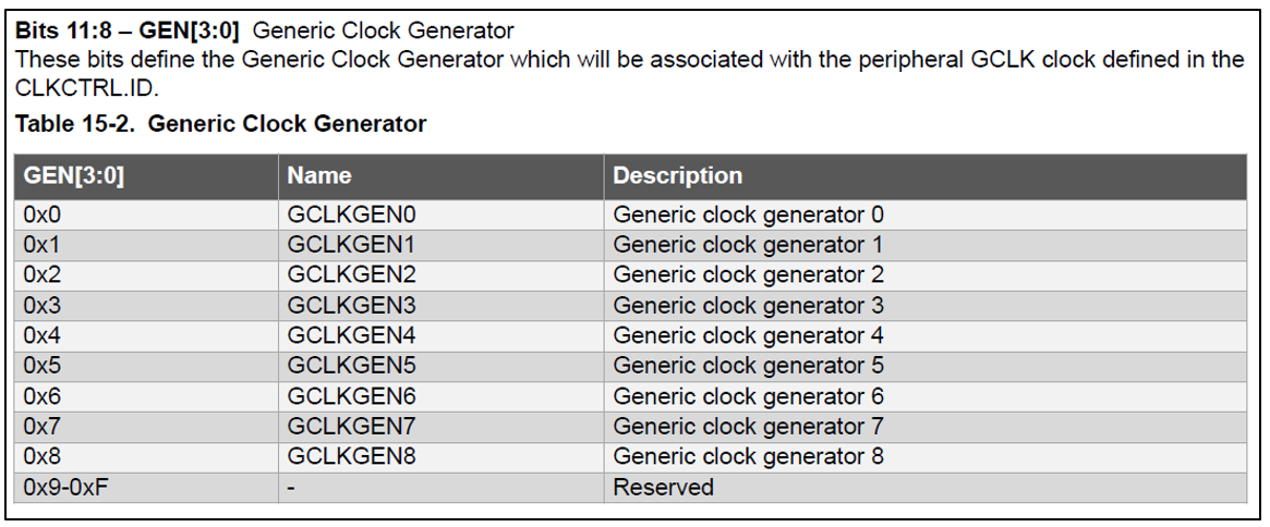
Generic clock generator 4을 사용합니다.
③ GCLK_CLKCTRL_ID_TC4_TC5
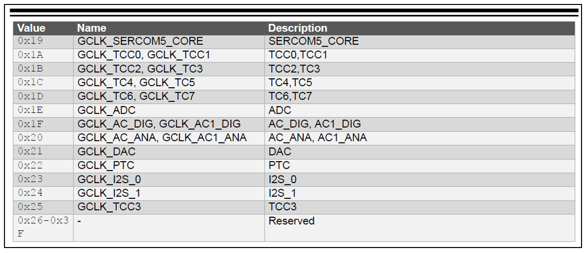
TC4(Timer Counter), TC5(Timer Counter)를 사용합니다.
정리하면 GCLK를 활성화시키고, Generic clock generator 4의 클럭 생성기를 통해 TC4(Timer Counter), TC5(Timer Counter)를 사용하겠다는 의미입니다.
여기서는 TC4을 사용했습니다.
4) TC4->COUNT16.CTRLA.reg |= TC_CTRLA_MODE_COUNT16 | TC_CTRLA_WAVEGEN_MFRQ | TC_CTRLA_PRESCALER_DIV256;
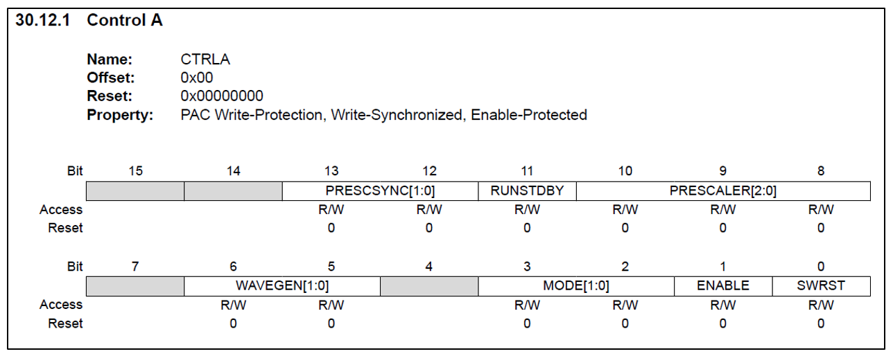
① TC_CTRLA_MODE_COUNT16

16bit 타이머를 사용합니다.
② TC_CTRLA_WAVEGEN_MFRQ
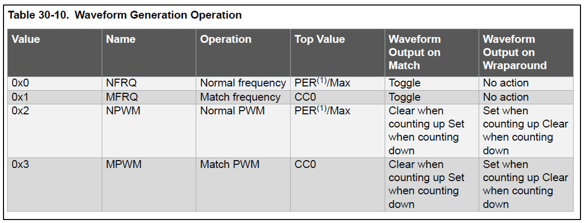
파형 출력 작업을 Match frequency로 합니다.
NPWM 또는 NFRQ 구성인 경우에는 16bit 및 32bit 카운터 모드에서 TOP 카운터가 최대 값으로 고정되지만 MFRQ는 TOP 카운터가 고정되지 않습니다.(SAM-D21 p562 참고)
※ Normal frequency와 Match frequency
Normal frequency의 주기 시간(T)은 PER 레지스터에 의해 제어됩니다.
Match frequency 주기 시간(T)은 CC0 레지스터에 의해 제어됩니다.
38.6.2.6.1 Waveform Output Operations
The compare channels can be used for waveform generation on output port pins. To make the waveform available on the connected pin, the following requirements must be fulfilled: Choose a waveform generation mode in the Waveform Generation Operation bit in t
onlinedocs.microchip.com
③ TC_CTRLA_PRESCALER_DIV256

Prescaler를 256으로 합니다.
정리하면 16bit 타이머, 주기 시간이 CC0 레지스터에 의해 제어되는 Match frequency, Prescaler는 256로 사용하겠다는 의미입니다.
5) TC->COUNT16.CC[0].reg = 62500;
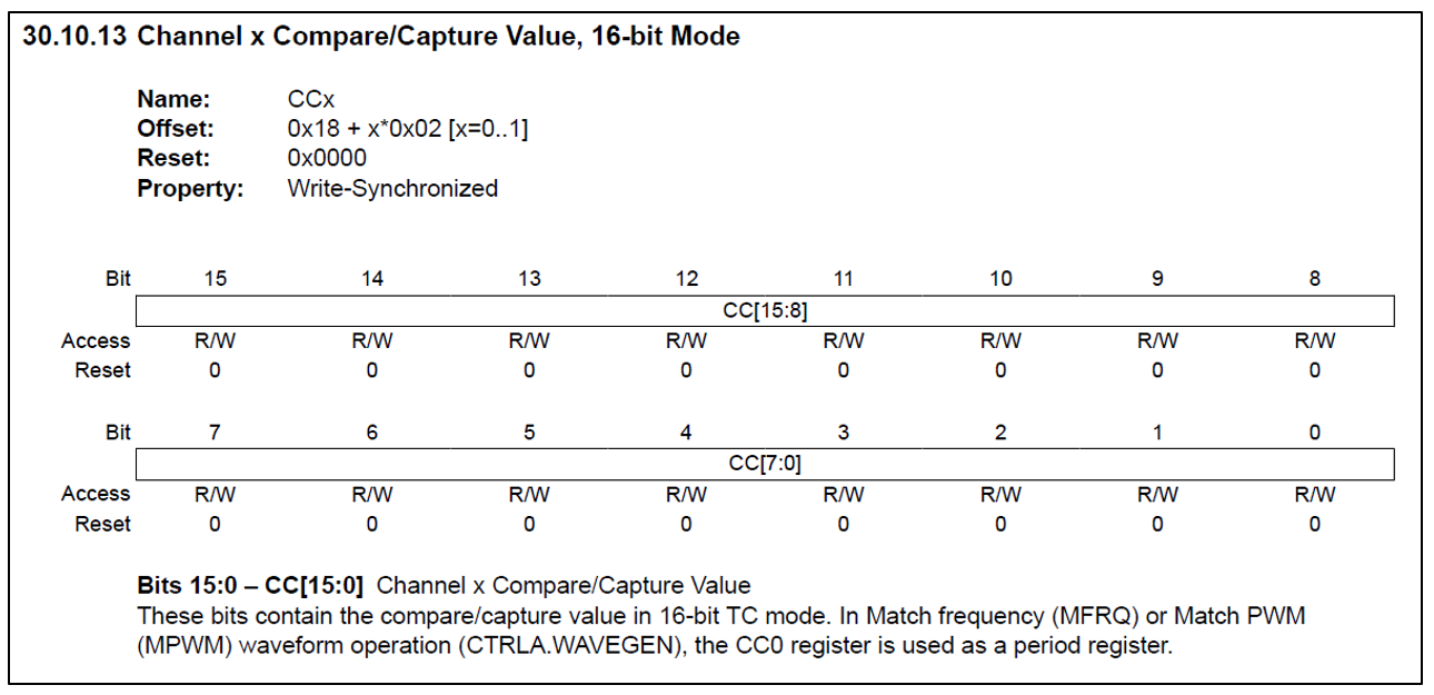
CC0 레지스터에 Compare/Capture Value 값을 62500으로 합니다.
정리하면 위에서 Prescaler는 256이므로 clock이 256번 뛸 때 1번 뛰는 것으로 계산됩니다.
주기를 결정하는 CC0의 Value가 62500이므로 0 ~ 62499까지 62500번 뛰어야 1카운트가 됩니다.
즉, 256 * 62500 = 16,000,000이므로 여기서 설정한 타이머는 1주기에 clock이 16,000,000 뜁니다.
그리고 GCLK은 DFLL48M / 6 (8MHz)를 사용하므로 16,000,000번 뛰는 데 걸리는 시간은 2초입니다.
결론적으로 여기까지 설정한 타이머의 주기는 2초입니다.
<타이머 주기에 따른 참고 자료>
https://powerdeng.tistory.com/210
타이머 설정 - STM32F030F4P6
MCU는 STM32F030F4P6을 사용하였고 관련 데이터 시트는 아래 첨부했습니다. STM32CubeMX 설정 1) 타이머 선택 및 활성화 범용 타이머인 TIM14를 선택한 뒤 Activated를 체크한다. 2) Prescaler(PSC) 타이머에 공급
powerdeng.tistory.com
6) TC4->COUNT16.INTENSET.bit.MC0 = 1;
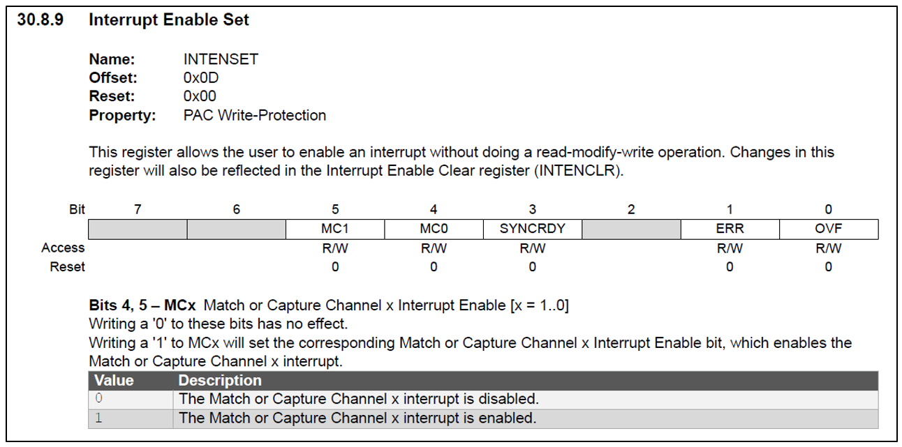
타이머 값이 비교 채널 0(MC0)에 설정된 값과 일치할 때 타이머/카운터4 모듈에 대한 인터럽트를 활성화합니다.
7) NVIC_EnableIRQ(TC4_IRQn);
NVIC(Nested Vector Interrupt Controller)에서 인터럽트를 활성화합니다.
최종 테스트 코드
unsigned char timerStopFlag = 0;

void Timer_Init() {

  /** Divide the 48MHz clock source by divisor 6: 48MHz/6=8MHz, Select Generic Clock (GCLK) 4 */
  GCLK->GENDIV.reg = GCLK_GENDIV_DIV(6) | GCLK_GENDIV_ID(4);
  while (GCLK->STATUS.bit.SYNCBUSY);

  /** Set the duty cycle to 50/50 HIGH/LOW, Enable GCLK4, Set the 48MHz clock source, Select GCLK4 */
  GCLK->GENCTRL.reg = GCLK_GENCTRL_IDC | GCLK_GENCTRL_GENEN | GCLK_GENCTRL_SRC_DFLL48M | GCLK_GENCTRL_ID(4);
  while (GCLK->STATUS.bit.SYNCBUSY);

  /** Enable GCLK4, Feed the GCLK4 to TC4 and TC5 */
  GCLK->CLKCTRL.reg = GCLK_CLKCTRL_CLKEN | GCLK_CLKCTRL_GEN_GCLK4 | GCLK_CLKCTRL_ID_TC4_TC5;
  while (GCLK->STATUS.bit.SYNCBUSY);

  //counter in 16-bit mode, waveform generation operation for match frequency, 256 prescaler
  TC4->COUNT16.CTRLA.reg |= TC_CTRLA_MODE_COUNT16 | TC_CTRLA_WAVEGEN_MFRQ | TC_CTRLA_PRESCALER_DIV256;
  while (TC4->COUNT16.STATUS.bit.SYNCBUSY);

  // Set the compare and capture value of channel 0 of TC4 to 62500
  TC4->COUNT16.CC[0].reg = 62500;
  while (TC4->COUNT16.STATUS.bit.SYNCBUSY);

  //Enables an interrupt for the Timer/Counter4 module when the timer value matches the value set in Compare Channel 0 (MC0).
  TC4->COUNT16.INTENSET.bit.MC0 = 1;

  // Connect TC4 to Nested Vector Interrupt Controller (NVIC)
  NVIC_EnableIRQ(TC4_IRQn);
}

void Timer_Start() {
  // Start the timer
  TC4->COUNT16.CTRLA.bit.ENABLE = 1;
  while (TC4->COUNT16.STATUS.bit.SYNCBUSY)
    ;
}

void Timer_Start_IT() {
  // Start the timer
  TC4->COUNT16.CTRLA.bit.ENABLE = 1;
  while (TC4->COUNT16.STATUS.bit.SYNCBUSY)
    ;

  //Enables an interrupt for the Timer/Counter4 module when the timer value matches the value set in Compare Channel 0 (MC0).
  TC4->COUNT16.INTENSET.bit.MC0 = 1;

  // Connect TC4 to Nested Vector Interrupt Controller (NVIC)
  NVIC_EnableIRQ(TC4_IRQn);
}

void Timer_Stop_IT() {
  // Stop the timer
  TC4->COUNT16.CTRLA.bit.ENABLE = 0;
  while (TC4->COUNT16.STATUS.bit.SYNCBUSY)
    ;

  //Disables an interrupt for the Timer/Counter4 module when the timer value matches the value set in Compare Channel 0 (MC0).
  TC4->COUNT16.INTENSET.bit.MC0 = 0;

  // Disconnect TC4 to Nested Vector Interrupt Controller (NVIC)
  NVIC_DisableIRQ(TC4_IRQn);
}

void setup() {
  // put your setup code here, to run once:
  Serial.begin(115200);
  while (!Serial) {
    for (unsigned char i = 0; i < 20; i++) {
      delay(100);
    }
    break;  /// about 2 sec
  }

  Timer_Init();
  Timer_Start_IT();
  Serial.println("Timer Start");
}

void loop() {
  // put your main code here, to run repeatedly:
  unsigned long curr;
  static unsigned long sPrevTimerStop = 0;

  if (timerStopFlag == 1) {
    curr = millis();

    if (sPrevTimerStop == 0) sPrevTimerStop = millis();

    if (curr - sPrevTimerStop >= 10000) {
      Serial.println("Timer Start");
      sPrevTimerStop = 0;
      timerStopFlag = 0;
      Timer_Start_IT();
    }
  }
}

void TC4_Handler() {
  static int count = 0;
  if (TC4->COUNT16.INTFLAG.bit.MC0) {
    Serial.printf("Timer Interrupt: %d\n", count++);

    if (count >= 50) {
      Serial.println("Timer Stop");
      count = 0;
      timerStopFlag = 1;
      Timer_Stop_IT();
    }
    TC4->COUNT16.INTFLAG.bit.MC0 = 1; // Clear the interrupt flag
  }
}
프로그램이 시작되면 타이머 인터럽트를 시작하여 2초마다 0부터 50까지 출력한다.
그리고 타이머 인터럽트가 해제되어 10초 기다린다.
10초가 지나면 다시 타이머 인터럽트를 시작하여 2초마다 0부터 50까지 출력한다.
이를 반복한다.
<코드 첨부 파일>
'개발환경 > Arduino IDE' 카테고리의 다른 글
| 아두이노 1대 N - RS485 통신 테스트 (1) | 2023.11.26 |
|---|
